[ -- 10% ]
Status: Planning
So often do I wish that cars had brake lights that not only indicated the car was braking, but that they also indicated how quickly they were braking.
Luckily, my car already has a wing with a set of LEDs embedded into it. They are wired to all come on at the same time, but it wouldn’t be too much work to convert them to be addressed individually or in groups of two.
A few things I have mulled over for some time are:
- The LEDs should light up from left (weak braking) to right (very hard braking) – ascending from left to right is intuitive for Americans
- There should be one or two LEDs lit on the right whenever the brake is pressed – this gives a reference point for the maximum pressure so drivers can gauge how hard the braking is
- All of the LEDs should blink several times and then burn solid when the max braking pressure has been met or exceeded (within the allowances of the California vehicle code) – blinking lights illustrates “Hazard!” or “Stay alert” which is exactly what we want in a hard-braking situation
- The LEDs should not blink at max pressure for several seconds after having already been reached – to act as coarse grained debouncing and to prevent continuous blinking
- If the controller fails, the fail-safe operation should be that all LEDs light whenever the brake lights are lit (this is the stock operation) – better to have them fail into stock mode than to fail always on or always off
This would give an experience like this:
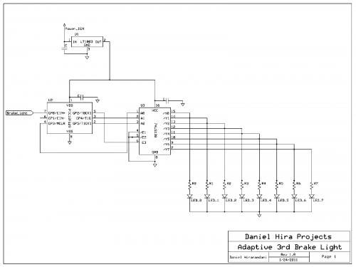
Now how can we accomplish this? Basically, we just need a power regulator, a microcontroller, a multiplexer to enumerate the outputs we want to address (individual LEDs), and to tape into the line that illuminates the brake lights. It’s much safer to tap into the brake light line as opposed to the braking line going into the ECU because it one malfunctions you end up with no brake lights, whereas the other one malfunctioning means bad things for an expensive ECU (which could affect ABS too..).
Here’s a version 1 schematic that includes everything except for the failsafe mode.
Taking the failsafe requirements into account, the best I can think of at this point would be to have the BrakeLight input and the output for the MSB LED (max braking pressure LED) fed into an AND gate which would then go into buffers with enable lines (basically, a selector), and each LED having two of these selecting buffers. If the output from the AND gate is high, then the buffers fed with the adaptive brake light signal would be selected. On the other hand, if the output from the AND gate is low, then the default BrakeLight input could be selected. This would still introduce more hardware which could fail (the AND gate and each of the buffers), but they would arguably be more dependable than the microcontroller.
This post is under construction; check back later for more content.

